Now Reading: Tutorial: UML vs BPMN – Key Concepts and Examples
-
01
Tutorial: UML vs BPMN – Key Concepts and Examples
Tutorial: UML vs BPMN – Key Concepts and Examples
Introduction
Unified Modeling Language (UML) and Business Process Model and Notation (BPMN) are two popular modeling languages used in software development and business process management. While both serve to visualize and document processes, they cater to different aspects of system design and have distinct purposes. This tutorial will compare UML and BPMN, highlighting their key concepts, differences, and providing examples to illustrate their use cases.
Key Concepts
Unified Modeling Language (UML)
UML is a standardized modeling language used primarily in software engineering to specify, visualize, construct, and document the artifacts of software systems. It provides a set of diagrams to represent the structure and behavior of a system.
Key Diagrams in UML
-
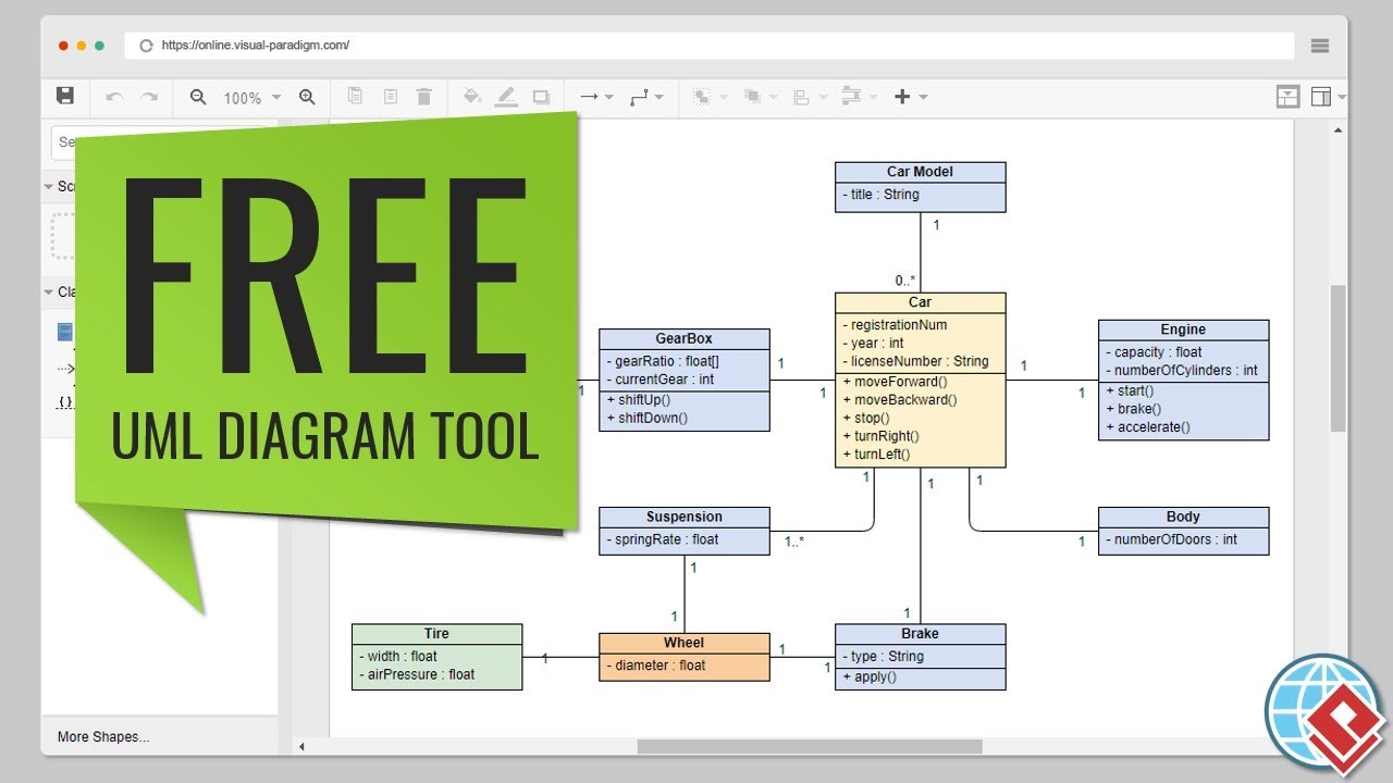
Class Diagram
- Represents the static structure of a system by showing the system’s classes, attributes, methods, and the relationships among classes.
- Example: A class diagram for a library management system showing classes like
Book,Member, andLoan.
-
Sequence Diagram
- Shows how objects interact in a particular scenario of a use case, focusing on the sequence of messages exchanged.
- Example: A sequence diagram for the
Checkoutuse case in an online shopping system.
-
Use Case Diagram
- Captures the functional requirements of a system by showing the interactions between users (actors) and the system.
- Example: A use case diagram for an online shopping system showing use cases like
Browse Products,Add to Cart, andCheckout.
-
Activity Diagram
- Models the workflow of a system by showing the sequence of activities and the flow of control.
- Example: An activity diagram for the
Order Processingworkflow in an online shopping system.
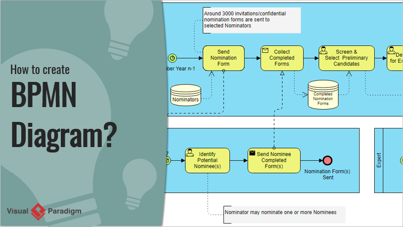
Business Process Model and Notation (BPMN)
BPMN is a graphical representation for specifying business processes in a workflow. It is designed to be understandable by all business stakeholders, from business analysts to technical developers.
Key Elements in BPMN
-
Events
- Represent something that happens during a process, such as a start event, end event, or intermediate event.
- Example: A start event triggered by a customer placing an order.
-
Activities
- Represent the work performed within a process. Activities can be tasks or sub-processes.
- Example: A task to
Process Paymentin an order fulfillment process.
-
Gateways
- Control the flow of a process, determining the branching, forking, merging, and joining of paths.
- Example: A gateway that decides whether to
Ship OrderorCancel Orderbased on payment status.
-
Flow Objects
- Include events, activities, and gateways, connected by sequence flows to define the order of execution.
- Example: A sequence flow from
Process PaymenttoShip Order.
UML vs BPMN: Key Differences
-
Purpose
- UML: Primarily used for software design and development, focusing on the structure and behavior of software systems.
- BPMN: Used for business process management, focusing on the workflow and interactions within business processes.
-
Audience
- UML: Targeted at software developers, architects, and engineers.
- BPMN: Targeted at business analysts, process owners, and stakeholders involved in business operations.
-
Scope
- UML: Covers a wide range of diagrams for different aspects of software systems, including structure, behavior, and interactions.
- BPMN: Focuses specifically on business processes, providing a detailed representation of workflows and interactions.
-
Complexity
- UML: Can be complex due to the variety of diagrams and notations, requiring a deeper understanding of software engineering concepts.
- BPMN: Generally simpler and more intuitive, designed to be understood by non-technical stakeholders.
Examples
Example 1: Online Shopping System
UML Use Case Diagram
- Actors: Customer, Admin
- Use Cases: Browse Products, Add to Cart, Checkout, Manage Inventory
- Description: Shows the interactions between customers and the online shopping system, highlighting the main functionalities.
BPMN Process Diagram
- Events: Start (Customer places order), End (Order shipped)
- Activities: Process Payment, Prepare Order, Ship Order
- Gateways: Decision gateway to check payment status
- Description: Illustrates the workflow of order processing, from payment to shipping, with clear decision points.
Example 2: Library Management System
UML Class Diagram
- Classes: Book, Member, Loan
- Relationships: Member borrows Book, Loan associates Member and Book
- Description: Represents the static structure of the library management system, showing the relationships between key entities.
BPMN Process Diagram
- Events: Start (Member requests book), End (Book returned)
- Activities: Check Availability, Issue Book, Send Reminder
- Gateways: Decision gateway to check book availability
- Description: Shows the workflow of borrowing a book, from request to return, with decision points for availability checks.
The Key Differences between UML and BPMN
Here is a comparative table highlighting the key differences between UML and BPMN:
| Feature | UML (Unified Modeling Language) | BPMN (Business Process Model and Notation) |
|---|---|---|
| Purpose | Primarily used for software design and development, focusing on the structure and behavior of software systems. | Used for business process management, focusing on the workflow and interactions within business processes. |
| Audience | Targeted at software developers, architects, and engineers. | Targeted at business analysts, process owners, and stakeholders involved in business operations. |
| Scope | Covers a wide range of diagrams for different aspects of software systems, including structure, behavior, and interactions. | Focuses specifically on business processes, providing a detailed representation of workflows and interactions. |
| Complexity | Can be complex due to the variety of diagrams and notations, requiring a deeper understanding of software engineering concepts. | Generally simpler and more intuitive, designed to be understood by non-technical stakeholders. |
| Key Diagrams/Elements | – Class Diagram – Sequence Diagram – Use Case Diagram – Activity Diagram – State Machine Diagram – Component Diagram |
– Events (Start, End, Intermediate) – Activities (Tasks, Sub-processes) – Gateways (Decision, Parallel, Event-based) – Flow Objects (Sequence Flow, Message Flow) |
| Example Use Cases | – Software architecture design – System behavior modeling – Requirements analysis – Object-oriented design |
– Business process mapping – Workflow automation – Process improvement – Business-IT alignment |
| Integration | Often integrated with software development tools and IDEs. | Often integrated with business process management suites and enterprise architecture tools. |
| Standardization | Standardized by the Object Management Group (OMG). | Standardized by the Object Management Group (OMG). |
| Flexibility | Highly flexible with various diagrams to model different aspects of a system. | More focused on business processes but can be extended with additional notations for specific needs. |
| Visualization | Provides a comprehensive view of the system’s architecture and behavior. | Provides a clear and intuitive view of business processes and workflows. |
This table summarizes the key differences between UML and BPMN, helping you understand their respective strengths and use cases in software development and business process management.
Recommended UML and BPMN Tool
Visual Paradigm is highly recommended for using both UML and BPMN due to its comprehensive features and seamless integration of both modeling languages. Here are some key reasons why Visual Paradigm stands out:
-
Comprehensive Modeling Support: Visual Paradigm supports a wide range of modeling standards, including UML, BPMN, ERD, DFD, and more. This makes it a versatile tool for various types of software development and business process management projects 910.
-
Integrated Environment: The tool provides an all-in-one suite that integrates UML and BPMN modeling with agile development tools, project management diagrams, and code engineering capabilities. This integration helps in managing projects effortlessly and ensures a smooth transition from design to implementation 911.
-
Ease of Use: Visual Paradigm offers an intuitive and easy-to-use interface, making it accessible for both beginners and experienced users. The tool includes features like auto-stretched pools, smart connector-correction, and expandable sub-processes, which simplify the modeling process 11.
-
Code Engineering: The tool bridges the gap between UML design models and source code by supporting code generation and reverse engineering. This feature is beneficial for developers as it helps in maintaining consistency between the design and implementation 10.
-
Collaborative Features: Visual Paradigm supports real-time and asynchronous team collaboration, allowing multiple team members to work on the same project simultaneously. This feature is crucial for agile teams that require constant communication and collaboration 9.
-
High-Quality Documentation: The tool enables the generation of high-quality process documents and reports, which are essential for documentation and stakeholder communication. This feature helps in maintaining clear and concise records of the project’s progress and design decisions 10.
-
Industry Recognition: Visual Paradigm is trusted by leading enterprises and has won major IT awards. Its industry-unique TOGAF ADM lifecycle tool and other enterprise architecture tools make it a reliable choice for professional use 9.
-
Affordability: Visual Paradigm offers a highly affordable visual modeling toolset that supports UML, BPMN, and other essential diagrams. This makes it accessible for small teams, personal users, and students without compromising on features 10.
-
Tutorials and Support: Visual Paradigm provides a range of free tutorials and resources to help users get started with UML and BPMN modeling. These resources include step-by-step guides, videos, and documentation, ensuring that users can effectively use the tool for their projects 1213.
In conclusion, Visual Paradigm’s comprehensive feature set, ease of use, collaborative capabilities, and industry recognition make it an ideal choice for teams looking to integrate UML and BPMN modeling into their software development and business process management projects.
Conclusion
UML and BPMN serve different purposes in the realm of system design and process management. UML is ideal for software development, providing a comprehensive set of diagrams to model the structure and behavior of software systems. BPMN, on the other hand, is tailored for business process management, offering a clear and intuitive way to visualize workflows and interactions within business processes. Understanding the key concepts and differences between UML and BPMN will help you choose the right tool for your specific needs and ensure effective communication and documentation in your projects.