Now Reading: Comprehensive Guide to Unified Modeling Language (UML)
-
01
Comprehensive Guide to Unified Modeling Language (UML)
Comprehensive Guide to Unified Modeling Language (UML)
Introduction to UML
Unified Modeling Language (UML) is a standardized modeling language consisting of an integrated set of diagrams designed to help you visualize the design of a system. UML is widely used in software engineering to specify, visualize, construct, and document the artifacts of software systems. It provides a standard way to visualize a system’s architectural blueprints, including elements such as actors, processes, activities, logical groupings, annotations, and so on.
Key Concepts
1. Model
A model in UML is a simplified representation of a system or a part of a system. It helps in understanding and communicating the design and structure of the system.
2. Diagrams
UML diagrams are graphical representations of a system’s architecture. They are categorized into two main types: structural diagrams and behavioral diagrams.
3. Elements
UML elements are the basic building blocks used to create models. They include classes, objects, interfaces, components, nodes, use cases, actors, and more.
4. Relationships
Relationships in UML define how elements are connected to each other. Common relationships include associations, generalizations, dependencies, and realizations.
5. Notations
UML uses a standard set of notations to represent different elements and relationships. These notations help in creating consistent and understandable diagrams.
Diagram Types
UML consists of 14 types of diagrams, which are divided into two main categories: structural diagrams and behavioral diagrams.

Structural Diagrams
-
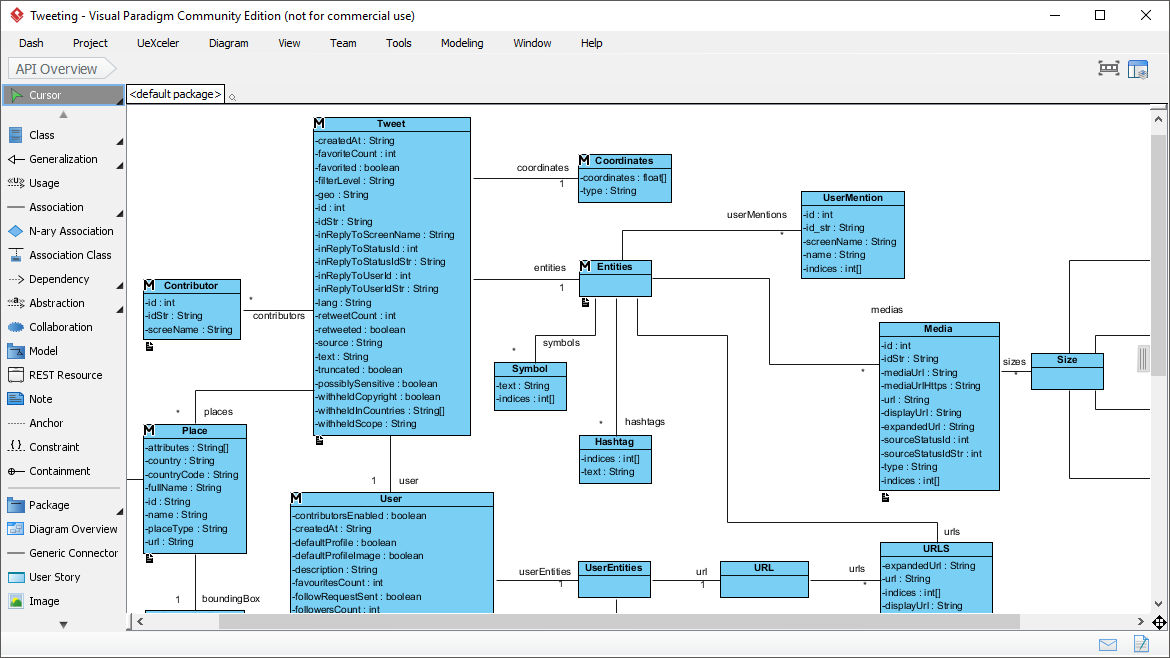
Class Diagram
- Represents the static structure of a system by showing the system’s classes, attributes, methods, and the relationships among classes.
- Example: A class diagram for a library management system showing classes like
Book,Member, andLoan.
-
Object Diagram
- Shows a snapshot of the detailed state of a system at a particular point in time.
- Example: An object diagram representing instances of
BookandMemberclasses in a library system.
-
Component Diagram
- Illustrates the organization and dependencies among a set of components.
- Example: A component diagram for a web application showing components like
UI,Business Logic, andDatabase.
-
Deployment Diagram
- Shows the physical deployment of artifacts on nodes.
- Example: A deployment diagram for a web application showing servers, databases, and their interactions.
-
Package Diagram
- Organizes elements of a model into groups, providing a way to structure and manage complex systems.
- Example: A package diagram for a software project showing packages like
UI,Services, andData Access.
-
Profile Diagram
- Customizes UML models with standard extension mechanisms.
- Example: A profile diagram extending UML for a specific domain like healthcare or finance.
Behavioral Diagrams
-
Use Case Diagram
- Captures the functional requirements of a system by showing the interactions between users (actors) and the system.
- Example: A use case diagram for an online shopping system showing use cases like
Browse Products,Add to Cart, andCheckout.
-
Sequence Diagram
- Shows how objects interact in a particular scenario of a use case, focusing on the sequence of messages exchanged.
- Example: A sequence diagram for the
Checkoutuse case in an online shopping system.
-
Communication Diagram
- Emphasizes the structural relationships between objects and the messages they exchange.
- Example: A communication diagram for the
Checkoutuse case showing the interactions betweenCustomer,Order, andPaymentobjects.
-
State Machine Diagram
- Represents the states of an object and the transitions between states due to events.
- Example: A state machine diagram for a
Orderobject in an online shopping system.
-
Activity Diagram
- Models the workflow of a system by showing the sequence of activities and the flow of control.
- Example: An activity diagram for the
Order Processingworkflow in an online shopping system.
-
Interaction Overview Diagram
- Provides a high-level overview of the interactions between different parts of a system.
- Example: An interaction overview diagram for the
Order Processingworkflow showing the interactions betweenCustomer,Order, andPaymentcomponents.
-
Timing Diagram
- Shows the interactions between objects in a single axis representing time.
- Example: A timing diagram for the
Order Processingworkflow showing the timing of interactions betweenCustomer,Order, andPaymentobjects.
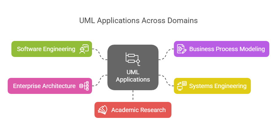
Applications Areas
UML is widely used in various domains and industries, including:
-
Software Engineering
- Software design and architecture
- Requirements analysis and specification
- System modeling and documentation
-
Business Process Modeling
- Workflow analysis and optimization
- Business process reengineering
-
Systems Engineering
- Hardware and software co-design
- Embedded systems development
-
Enterprise Architecture
- Enterprise-wide system integration
- IT strategy and planning
-
Academic Research
- Formal methods and verification
- Software engineering education
Examples
Example 1: Library Management System
-
Class Diagram
- Classes:
Book,Member,Loan - Relationships:
MemberborrowsBook,LoanassociatesMemberandBook
- Classes:
-
Use Case Diagram
- Actors:
Librarian,Member - Use Cases:
Borrow Book,Return Book,Search Catalog
- Actors:
-
Sequence Diagram
- Scenario:
Borrow Book - Objects:
Member,Librarian,Book,Loan - Messages:
Memberrequests to borrowBook,Librarianchecks availability,Loanis created
- Scenario:
Example 2: Online Shopping System
-
Class Diagram
- Classes:
Customer,Product,Order,Payment - Relationships:
CustomerplacesOrder,OrdercontainsProduct,PaymentprocessesOrder
- Classes:
-
Use Case Diagram
- Actors:
Customer,Admin - Use Cases:
Browse Products,Add to Cart,Checkout,Manage Inventory
- Actors:
-
Activity Diagram
- Workflow:
Order Processing - Activities:
Customer places order,Order is validated,Payment is processed,Order is shipped
- Workflow:
Conclusion
UML is a powerful and versatile modeling language that helps in visualizing, specifying, constructing, and documenting the artifacts of software systems. Its wide range of diagrams and standardized notations make it an essential tool for software engineers, business analysts, and system architects. By understanding the key concepts, diagram types, and application areas of UML, you can effectively use it to design and communicate complex systems.
Visual Paradigm is highly recommended as the best UML tool for IT software development teams due to its comprehensive suite of features and seamless integration with agile methodologies. Here are some key reasons why Visual Paradigm stands out:
-
Comprehensive Modeling Support: Visual Paradigm supports a wide range of modeling standards, including UML, SysML, BPMN, ERD, DFD, and ArchiMate. This makes it a versatile tool for various types of software development projects 123.
-
Agile Integration: Visual Paradigm is designed to aid agile software development processes. It integrates UML modeling with agile practices such as Scrum and Kanban, allowing teams to create UML diagrams as needed to support communication and documentation without compromising agility 45.
-
Collaborative Features: The tool supports real-time and asynchronous team collaboration, enabling multiple team members to work on the same project simultaneously. This feature is crucial for agile teams that require constant communication and collaboration 15.
-
Code Engineering Capabilities: Visual Paradigm offers code generation and reverse engineering capabilities, which can significantly speed up the development process. It supports various technologies such as ORM and REST, making it easier to transition from design to implementation 16.
-
User-Friendly Interface: The tool provides an intuitive and easy-to-use interface, which helps in creating and managing complex diagrams efficiently. It also includes features like wireframing, storyboarding, and prototyping, which are essential for UX design 15.
-
Integration with IDEs: Visual Paradigm integrates seamlessly with leading Integrated Development Environments (IDEs), ensuring a smooth transition from analysis to design and implementation. This integration reduces efforts across all stages of the software development lifecycle 7.
-
Reporting and Documentation: The tool allows for the generation of professional reports in various formats such as PDF, Word, and HTML. This feature is beneficial for documentation and stakeholder communication 8.
-
Industry Recognition: Visual Paradigm is trusted by millions of users, including government units, blue-chip companies, and educational institutions. It has won major IT awards, further validating its reliability and effectiveness in the industry 5.
In conclusion, Visual Paradigm’s robust feature set, agile integration, collaborative capabilities, and industry recognition make it an ideal choice for IT software development teams looking to enhance their UML modeling and software development processes.